
|
| "How To Series" #1 - 6/22/02 How to convert a .prt (Pro/Engineer) file into a .dwg (AutoCAD) format when sending files to DC Waterjet for CNC Waterjet cutting. |
This "How To" will cover step-by-step the process of making a correct scale .dwg file from your .prt files, for the folks at DC Waterjet. It is really only helpful to the Pro/Engineer users out there. I recently contacted Gary of DC Waterjet to get a quote on having the baseplate for my robot cut. Gary uses AutoCAD 2000, and I am using Pro/Engineer 2001. I had some difficulty converting my .prt file that I designed my baseplate in, into a usable .dwg file for Gary to use. I ended up contacting PTC tech support after banging my head against the wall for quite some time, and not making any progress towards getting a usable file. |
Big thanks to David @ PTC tech support for his help in figuring out this process, and to Gary @ DC Waterjet for being so patient with my trial and error emails! ;)
|
The first step in the conversion process, to start the creation of a .drw file in Pro/Engineer. Once you have started ProE, click on the "Create New" icon. |
 |
When the "new" window appears:
|
 |
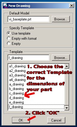
When the "New Drawing" window appears, click the "Browse" button from the "Default Model" field. |
 |
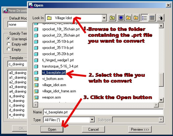
When the "Open" window pops up:
|
 |
You should now be back to the "New Drawing" window:
|
 |
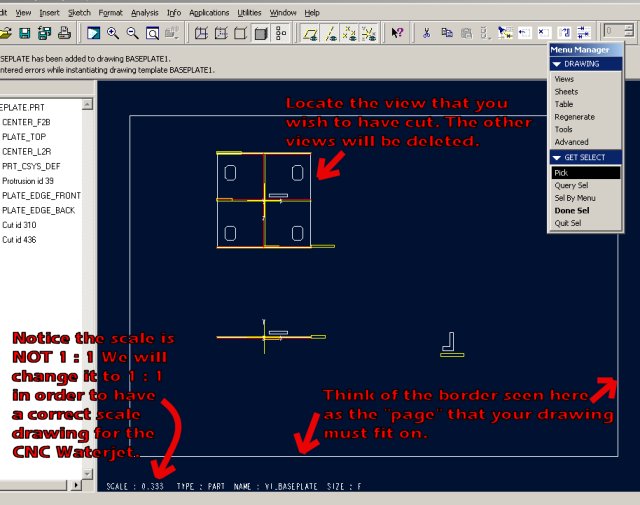
You should see a 2D rendering of your part now! We still have some work to do to make the scale correct, and get rid of what we do NOT want in the drawing. The border shown in the picture is like the borders of a "page". When we are finished, our part will need to be within the borders of the page. We also need to make the SCALE of the part 1:1 so it will be cut to the correct dimensions. You can see in the bottom left of this picture, that my part is only 1/3 (.333) scale. So if I converted the drawing to .dwg and sent it off to DC Waterjet as is, I would get a 7.66" x 7.66" baseplate back! So the scale aspect is VERY important. Lastly, we need to delete every view of our part, EXCEPT the one we wish to have cut. For my baseplate, the view in the top left is the one I want to keep. |
 |
The next step is to correct the scale of the part. When we are finished, we will have a 1:1 scale, so when we send a file to DC Waterjet, we get the right sized part!
|
 |
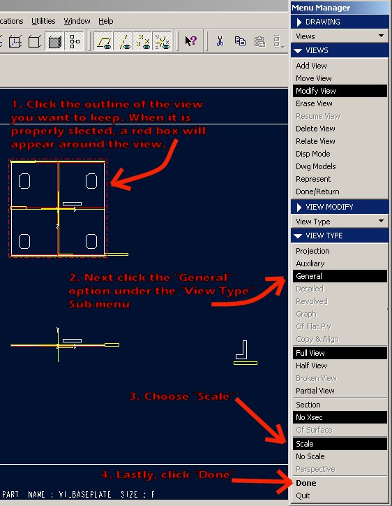
Click on "Modify View" in the "Menu Manager". |
 |
Click on "View Type" in the "Menu Manager". |
 |
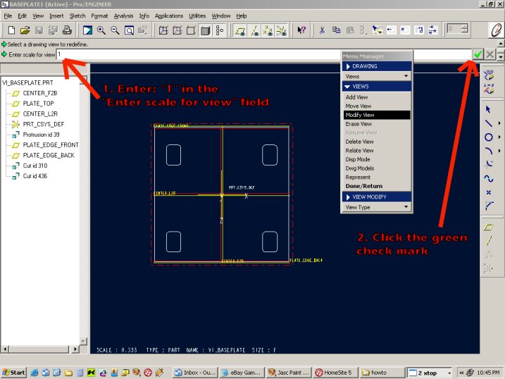
Now we are ready to resize the view we want to keep, to the proper scale.
|
 |
Almost finished with the re-scale.
|
 |
Click "Done/Return". |
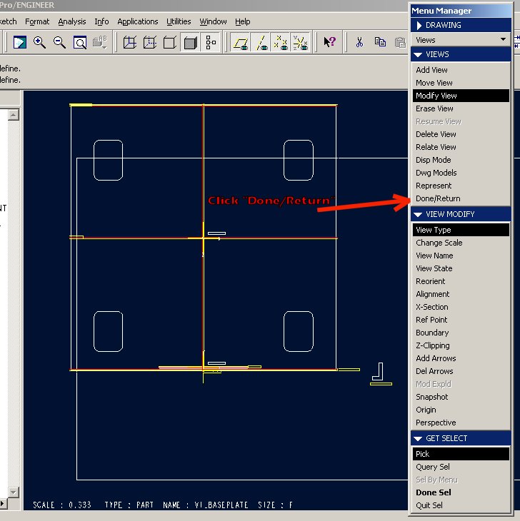 |
By now, you should see a difference in the scale of your part. In my case, it made the view of the baseplate that I wanted to keep dramatically larger. Next we need to move the view to where it is not on top of any of the other views, as we will be DELETING the other views. If in your case, the view you changed the scale on is NOT over top of another view, then you may skip to the next step.
|
 |
Click "Views" under the "Menu Manager. |
 |
Hang in there, we are getting close! I know this entire how-to report is likely WAY to in-depth (considering you DO know enough about ProE to make the .prt file in the FIRST place!), but I try to design these types of things to where ANYONE could walk their way through the process.
|
|
Click "Done/Return". |
|
Select the backwards "L" shape by left clicking on it. |
 |
Right click and HOLD the button in over top of the backwards "L" shape to get the menu shown in the screen capture. Chose "Delete" from the menu. The backwards "L"will still show up as gray, but trust me, it's gone. ;) |
 |
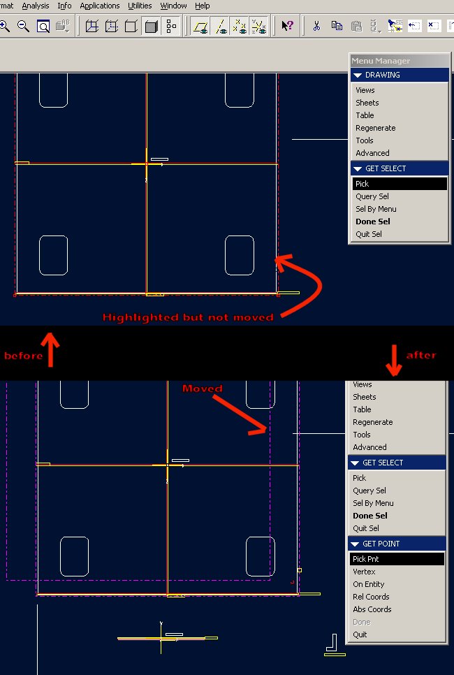
Now to move the last view back into the center of the drawing page.
|
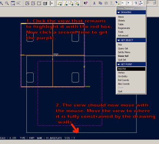 |
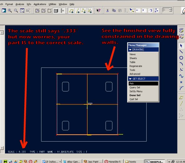
Almost done! If everything has been done properly, you should see the actual part you want to have cut, in the center of the drawing. It should be fully constrained by the drawing walls as shown in this screen capture. |
 |
Woohoo! We are done! All that's left to do, is save the file, "Save a Copy" in the .dwg file format, email the file to Gary @ DC Waterjet then wait for your COOL new part to show up at your door ;)
|
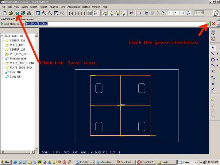 |
Last couple of steps. The file is saved in .drw format, but we need a .dwg for DC Waterjet. The conversion process is a simple one from here.
|
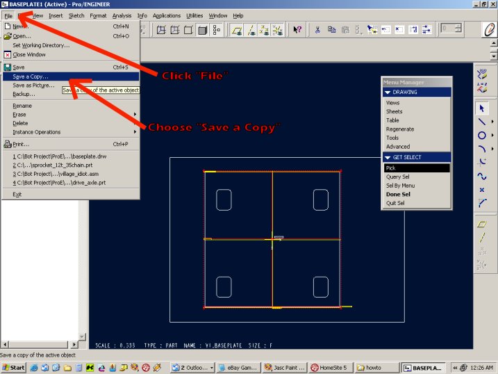 |
Last step! This is it, when you are finished with this one fire up the email and send the new .dwg file over to DC Waterjet for cutting!
You should now have the file we just created easily accessible in the directory you just saved it in. Attach it to an email and you are on your way towards having a custom, inexpensive, quality part from DC Waterjet. |
 |